

How To Draw A Robot Arm
Exploring Drawing Techniques with a Robotic Arm
The participation of robots into the social sphere of homo life is currently limited to driverless cars and has not affected more mundane tasks. An average office or workplace is void of robots, with clerical staff committed to organizing workspace, cleaning, delivering packages, and and so on. With an exception of automated vacuum cleaners, American homes are also devoid of robotic technology. Increasing the domestication of robotic technology, would certainly enhance involvement in the field of robotics from the general public.
To explore robotic participation in more usual tasks, our squad considered how a robotic arm can benefit us, equally engineers, on a regular day. Engineers are not known for their exemplary cartoon and artistic abilities. Many have shy'd abroad from writing utensils since the dawn of the keyboard and touch screen. However, information technology is still convenient to exist able to produce quick sketches that that tin can be passed to project managers, bosses, and other superiors that may not be able to interpret our chicken scratches. To find a replacement for the engineering hand, the Dobot Arm V1.0 was used.
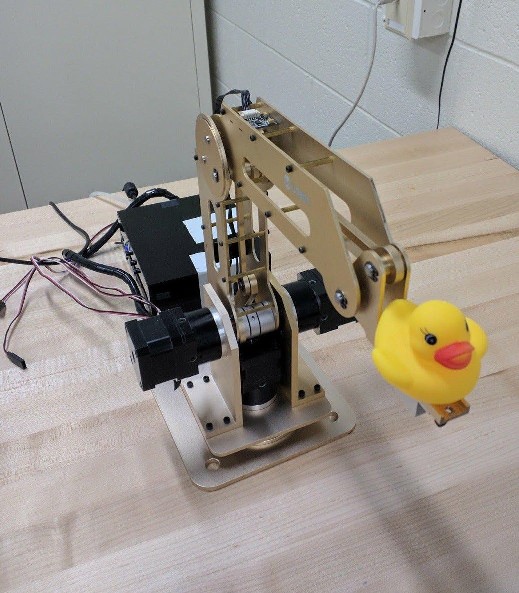
The Dobot Arm V1.0 is a relatively pocket-size three degree-of-liberty (DOF) robotic arm. The arm is produced by a Chinese company by the name of Shenzhen Yuejiang Technology Co. Ltd. The arm is designed with teaching and small projects peculiarly in mind.
In terms of hardware functionality, the arm is rather limited. The end effector (Represented with duck in the left picture) of the arm can be substituted with grasping claw, a suction pump, or a writing utensil. This is perfect for the scope of this project. The joints of the arm accept relatively depression angles of freedom. The end effector of the robot is fixed relative to the first joint and the second and tertiary joint of the robot are related to each other.
In order to more directly translate Robotic kinematic concepts to the Dobot, MATLAB 2017 was used. MATLAB is especially intuitive for working with matrices. A MATLAB library, known equally Robot Raconteur was used to communicate and send articulation angles to the Dobot. Additionally, MATLAB comes with a plethora of useful image processing tools. Due to the nature of the project, image processing methods were necessary.
Kinematics
When programming robots, it's necessary to represent the robot in a mathematical model. Without a model that a robot can be programmed by, the robot is but a hunk of metal with some wasted motors.
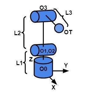
The picture to the right represents such a model of the robot. This representation of the Dobot gives structure to the robot and allows u.s.a. to program the exact position the end effector needs to move to. The forward kinematic equations of the robot are shown beneath. These equations allows for the end effector position to be found if the joint angles are known. Unfortunately, angles are hardly always known and are usually what need to be plant. Bold the Cartesian x,y, and z coordinates are known, the forwards kinematics can exist used to derive the changed kinematics. For the sake of brevity, this derivation is non displayed.
Drawing
The initial cartoon technique that was explored was based on intuition. When a human draws they put their hand downwards and draw betwixt points. We all learned this method from a child-hood game known as connect the dots. The image detection method of connect-dots is known as corner detection. With corner detection, an assortment of random points were found in an image. The points were ordered and and then used to draw.
While this technique worked fairly optimally with unproblematic shapes, it chop-chop ran into problems with more complicated shapes (i.e. 2d representation of a cube). Connecting the dots was the fastest method for cartoon. Unlike other methods of cartoon, corner detection never required removing the pen of off the surface of the newspaper.
Of course, well-nigh engineers sketch items that are slightly more circuitous than basic geometric shapes. Then corner detection was not the most optimal solution. Moving abroad from corner detection, information technology dawned on us that populating and unabridged image with points is redundant. When drawing straight edge pictures and artist only cares where a line starts and ends.
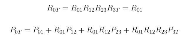
An alternative method for detecting an image was done using Hough (pronounced "Huff") Transforms to discover lines. This method required a rather elaborate algorithm of image manipulation which is summarized in the paradigm below. A standard blackness and white image was taken (A). The image was and then complemented for ameliorate contrast (B). To avoid repeated lines due to line width the skeleton of the image was taken (C). The skeleton reduced the lines to 1 pixel width lines. Line detection was iterated beyond the skeleton epitome until every line was found (C-E). Unfortunately, even after the processing that was done on the epitome, errors where still found (F). Some lines were too short or overlapped with other lines. An optimization algorithm was written too condense lines with like slopes and in similar regions (G). Finally, the Dobot was given a collection of starting and finish points of each line and drew the shape (H).
Line detection proved to be 1 of the most successful methods of drawing images. The lines came out shine unlike those in corner detection. The line detection method was successful in producing much more complex shapes that the robot was able to draw. These shapes involved multiple lines at corners, overlapping lines, and close parallel lines . The new strategy produced shapes that were smooth, unlike images produced using corner detection. Furthermore, the line detection method stored less points. Using line detection, the robot needed to know just two points per line. Corner detection involved multiple points for each line.
A articulate limitation is seen with line detection. If you give the Dobot a circumvolve, it would give you a quizzical response. Nosotros couldn't demonstrate drawing capabilities of a robot with out considering curved lines.
A method based on Probabilistic Road Mapping (PRM) was adult to depict circles. The method was like to corner detection in that information technology searched for points within a assorted line. Even so, the algorithm written fabricated an effort to brand splines between points that left the region of the circle. This created a more than curved like path. The algorithm was very rudimentary. Circles were recognizable simply crude, as can exist seen in the paradigm below. PRM worked with many shapes that could exist drawn with the same approaches.
Finally, the team wanted to be able to draw gradients. This is rather difficult to do, considering that a calligraphy pen had been used to draw upwardly to this point.
Gradients and shadows were represented through density of dots. An image was converted into gray-scale and then divided into sections. For each department an average grey-scale value was plant. The boilerplate grayness scale value was mapped to a density of dots value. Using this method gradient images were developed based on inserted images. An instance is shown below. This method was slow. Slow is an understatement. The paradigm below took over x minutes to produce. This is quite lengthy compared to the other methods used for drawing, which oftentimes took no longer than a xxx seconds to depict.
Vision
In order for a complex engineering to be accepted into social club it needs to be considerably simplified, better yet, democratic. The terminal part of the projection worked to make an autonomous scanning and printing system. A bones Logitech web camera was used and was represented using the standard pin-pigsty camera model.
The webcam was responsible for finding a drawn prototype. The camera specifically searched for a symbol (x,y-axis frame) and then cropped the captured image to exclude everything outside of the region that the creative person drew in. The webcam then searched for a region to draw in. A cartoon region was defined as the expanse in between four plus signs. The regions of highest correlation were simplified to 4 points, shown in the image below. The image that was designated to be drawn was and so scaled to fit the drawing region.
Results
Judging from the outcome of many of the drawings, printers may yet retain their annoying occupations in the office and home for awhile longer. Besides the obvious greater cost of current robotic arms, Robots are currently slower than printers. While a robot draws with a single pen, a printer colors in multiple points on a paper at one time. Not because fourth dimension, information technology was demonstrated that a robotic arm could perform many of the tasks a printer can. Through several drawing methods, including corner detection, line detection, PRM, and gradients, the Dobot displayed a robots ability to replicate the basics of graphic artistry. All this was implemented using rather fundamental elements of robotics, such as rigid-body kinematics and the pivot-hole model. A basic demonstration of a autonomous scanning system was developed equally a proof of concept with enough of room of optimization and improvement.

Source: https://theclassytim.medium.com/exploring-drawing-techniques-with-a-robotic-arm-464971f7c036
Posted by: rodriguezmolaing.blogspot.com
0 Response to "How To Draw A Robot Arm"
Post a Comment